CubeControl — final project

For my PS70 final project, I built a 3D Rubik's cube that works as a controller. You turn faces, hall sensors catch swipes, and the computer sees the move, recognizing the cube as a USB device. The goal of this project was to sense all the different swipes and make interesting cool macros with them, and use the rubik's cube as a USB device, or a sort of game controller
This documentation can be roughly divided into three parts:
- An overview of the final project
- A summary of the timeline
- A deep dive split into: mechanical design, software design, integration
Overview
Here is a video of me using CubeControl to play the classic dino game online
What I built
CubeControl is a Rubik's cube controller. You do moves on a real Rubik's cube and the Arduino code turns them into output that the computer then recognizes as a keypress. It feels like playing with a cube, not a separate keypad, and those swipes are translated into actual USB device outputs.
Early in the semester I also prototyped using an IMU for game control (week 7) and talked about wilder macro ideas — like a permutation opening a Google Doc. I didn't include that in the final project; what I completed was reliable magnet swipe sensing and a custom printed shell but it's something I'll continue working on in the future
Demo videos
Speed cube v1 — YouTube
Timeline
Week 5
Around week 5 I stopped treating the cube like a black box and started learning how rubik's cubes actually work. I bought a bunch of cheap cubes, took them apart, looked at the internal designs, and put them back together just to see how the pieces move relative to each other. I looked up the original designs of a Rubik's cube and took apart learnt how they worked. (Got my solve time down to a minute, if anyone cares)
After that the real problem showed up. Where do you even put a sensor? Everything rotated and the wires would snap. There isn't obvious empty space until you start cutting plastic. Another key questions I started grappling with, was how am I going to fit everything within the core of a rubiks cube when everything is usually so packed on the inside
Some ideas I started thinking about as an alternative were:- Using slip rings and keeping wiring in each physical portion of the cube
- Using rotary encoders that kept memory of state rather than change of state
- Some advice I got during MVP week was using a 2 by 2 cube, which I seriously explored, but looking into the internals made me realize that keeping it as a 3 by 3 cube was better for my goals. The 3 by 3 cube has invariant parts whereas every part of a 2 by 2 spins around
Week 8: Input and Output Measuring: MVP with enclosure
At this point I had realized that my main bottleneck would be 3D design and not complicated sensing. The question remained: how would I feasibly fit in sensors into a reasonable working Rubiks cube that was robust and well calibrated to sensors, and would detect bidirectional swipes, along with possible integration of buttons and an IMU sensor in a single shell?
Something important here was a pivot from the xiao esp32c3 to the xiaoesp32s3. The S3 version supports USB device connection while the C3 version doesn't support this. This was the week I focused on output and ensuring that the swipes could be translated to the output I wanted on the device.
Week 10-13: 3D Iteration and Fitting Sensors
By far the most demanding part of the project. Conceptually, everything worked so well. The hall sensing tech really impressed me. The A3144 digital hall effect sensors were able to detect magnets to a very high degree of accuracy. I'd become fairly familiar with the internals of Rubiks cubes and how the worked, but I needed improvements, which I began along with focusing on integrations
At this point, I pivoted to speed cube design because I wanted to learn how to make my cube faster and to prevent pieces from popping out when I twisted it quickly. I also wanted to support features such as corner cutting (twisting a face when another face hasn't fully settled), and adjusting the cube's tension using springs. (How much energy is needed to make a swipe)
I wrapped up the project, by refining the integration of the hall effect sensors into the design. I prototyped three different designs for integrating hall effect sensors. I ended up on a design that snapped the hall effect sensors into place described below

Mechanical design
Here is the process we used to mechanically design the Rubiks cubeAs the video above shows, we froze the bottom-left corner and hollowed it for the board, battery, and sensor wiring. Top and right faces still turn. That was enough expressivity without wiring every axis.
In Fusion we built speed-cube geometry, fused the fixed corner, and cut cavities for electronics. We iterated prints until we had a shell that fit the guts and still turned.
This video was super helpful in the foundation of speed cube design (although they use different software, you can get a good sense of what to do and you can approximate actions in what Fusion360 is able to do). It's a six part playlist on the intricacies of designing a speed cube. Shout out to NKCubed
I went through three different faces and tolerances to snap the hall effect sensors into place. I had a lot of difficulty in ensuring wires didn't intertwine and touch while inside the Rubiik's cube (burnt through at least 10 sensors). I then used heat shrinks to enclose the wires and burnt out more space in the print for the thicker wires using a solder (should have 3d printed but what's 2 mins vs 2 hours, that's the scrappy mentality PS70 has left with me Nathan)


Fusion model: share link
The invariant we landed on
Most of a cube spins. The design trick was deciding what stays fixed:
- Hall sensors live on parts that do not rotate (fixed shell / corner block).
- Magnets live on the rotating parts (edge pieces sweeping past in a circular path).
We started with ideas in the core, then moved to the corner enclosure when we ran out of wire room. That choice is what made the rest of the layout workable.
Software and Sensing
We used two digital hall sensors on the fixed plastic in a circular layout. Magnets on the edge pieces sweep past when you turn. Whichever sensor trips first sets the direction (A then B vs B then A). Same hardware path, different move.
Getting that stable took debouncing and non-blocking reads in firmware — no delay() in the final hall sketch. Commit 829c244 was when digital hall sensing came online (HallTestingCopyFile in the repo).
Basic hall sensing
Bidirectional swipes (which sensor fires first)

Schematic: arduino_circuit.png. Full sketch: final_code.ino
Two digital hall-effect sensors on D2 and D3 detect when magnets on the cube pass by. The hard part was telling swipe direction: same two sensors, but order matters.
Demo video
Recording of bidirectional swipe detection. One direction prints A -> B, the other B -> A.
Circuit schematic
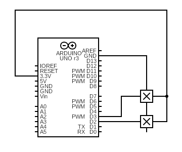
Hall sensors on D2 and D3 with internal pull-ups. Magnets on the cube pull the line LOW when they get close.
Full sketch
Setup & pins
Both halls are digital inputs with INPUT_PULLUP. The sensors I had printed a one when it senses a magnet nearby, and 0 otherwise.
const int hallA = D2;
const int hallB = D3;

const unsigned long debounceMs = 8;
const unsigned long swipeTimeoutMs = 400;

void setup() {
  Serial.begin(115200);
  pinMode(hallA, INPUT_PULLUP);
  pinMode(hallB, INPUT_PULLUP);
}
No blocking delay
Early tests used delay(10) in the loop and spammed Serial. I missed fast swipes and this made the timing feel flunky. The final loop never blocks but it polls every pass and tracks when each raw reading last changed, and only accepts a new stable level after debounceMs (8 ms) without another flip. I debounce by time instead of delay code.
if (rawA != lastA) {
  lastA = rawA;
  lastAChange = now;
}

if (rawB != lastB) {
  lastB = rawB;
  lastBChange = now;
}

if ((now - lastAChange) > debounceMs && rawA != stableA) {
  stableA = rawA;
  if (stableA == LOW) A_fall = true;
}

if ((now - lastBChange) > debounceMs && rawB != stableB) {
  stableB = rawB;
  if (stableB == LOW) B_fall = true;
}
This ended up being very reliable. Quick cube turns still registered clean A→B vs B→A strings on Serial without double-firing from bounce.
A_fall and B_fall
Each loop we reset two flags. A fall means sensor A just settled LOW (magnet hit A). Same for B. We only set the flag on a stable transition to LOW, not on every noisy read.
bool A_fall = false;
bool B_fall = false;

// ... debounce logic above sets A_fall / B_fall when stable goes LOW
One sensor firing alone starts a swipe. The second sensor firing completes it — that order is the direction.
Bidirectional swipe logic
firstSensor remembers who went first (1 = A, 2 = B). If nothing finishes within swipeTimeoutMs, we reset so a half-swipe doesn't stick around.
if (firstSensor != 0 && now - firstTime > swipeTimeoutMs) {
  firstSensor = 0;
}

if (firstSensor == 0) {
  if (A_fall && !B_fall) {
    firstSensor = 1;
    firstTime = now;
  } else if (B_fall && !A_fall) {
    firstSensor = 2;
    firstTime = now;
  }
} else if (firstSensor == 1 && B_fall) {
  Serial.println("A -> B");
  firstSensor = 0;
} else if (firstSensor == 2 && A_fall) {
  Serial.println("B -> A");
  firstSensor = 0;
}- A → B: A falls first and then B falls
- B → A: B falls first, then A (the other direction)
What we ended up with
- Learned speed-cube internals by tearing down retail cubes and reassembling them.
- Custom Fusion shell with a fixed corner enclosure for electronics.
- Magnets on rotating edges, hall sensors on fixed plastic — the invariant held through the final build.
- Bidirectional swipe detection in firmware.
- Printed cube, soldered sensing stack, schematic and sketch in
public/final/. - Documented demos: build timelapse, YouTube v1, swipe photo.
We scoped host tricks (Google Doc triggers, repeat-move typing) as a separate layer. The final project deliverable was the physical cube + sensing pipeline; week 7 covers the earlier IMU-to-game experiment.
What was hard
- Finding space for sensors without killing turn feel . We drew the paths
- Keeping sensors square to the magnet path in printed pockets.
- Telling R from R' when the same magnets pass both readers.
- Fitting wires through a cube that still has to scramble.
Related weekly docs
Earlier inspiration ideas
Brainstorms from earlier in the semester before CubeControl.
Iron Man helmet
3D printed helmet with an opening faceplate, maybe headphones inside. Stretch goal was the whole suit.
Collective art sketcher
Machine that takes photos, simplifies to line intensities, and draws so a community can fill it in like a coloring book. Came from a Lowell workshop on collaborative drawing.

Collective charcoal drawing with two people